Unless otherwise indicated, this handbook is based on a helicopter that has the following characteristics:
1 - An unsupercharged reciprocating engine.
2 - A single main rotor rotating in a counterclockwise direction (looking downward on the rotor).
3 - An antitorque (tail) rotor.
4 - Skid-type landing gear.
Information is intended to be general in nature and should apply to most helicopters having these characteristics.
Before launching into a detailed discussion of the various forces acting on a helicopter in flight, it is first necessary that you understand the meaning of a few basic aerodynamic terms, how the force of lift is created, and the effect that certain factors have on lift.
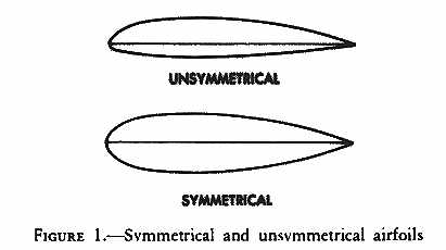
Airfoil - An airfoil is any surface designed to produce lift or thrust when air passes over it. Propellers and wings of airplanes are airfoils. Rotor blades on helicopters are airfoils. The wing of an airplane is normally an unsymmetrical airfoil, that is, the top surface has more curvature than the lower surface.
The main rotor blades of most helicopters are symmetrical airfoils; that is, having the same curvature on both upper and lower surfaces (fig. 1). Much research, however, is being conducted in the use of unsymmetrical airfoils for main rotor blades, and at least one currently manufactured make of helicopter is equipped with main rotor blades that are not considered true symmetrical airfoils.
On an unsymmetrical airfoil, the center of pressure is variable - as the angle of attack increases, the center of pressure moves forward along the airfoil surface; as the angle of attack decreases, the center of pressure moves rearward. On a symmetrical airfoil, center of pressure movement is very limited. A symmetrical airfoil is preferred for rotor blades so that a relatively stable center of pressure is maintained. Improvements in control systems may allow more latitude in blade designs in the future.
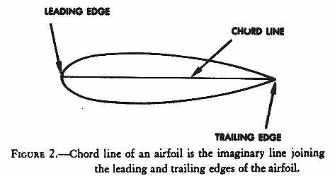
Chord line - The chord line of an airfoil is an imaginary straight line from the leading edge to the trailing edge of the airfoil (fig. 2).
Figure 1 - Symmetrical and unsymmetrical airfoils.
Figure 2 - Chord line of an airfoil is the imaginary line joining the leading and trailing edges of the airfoil.
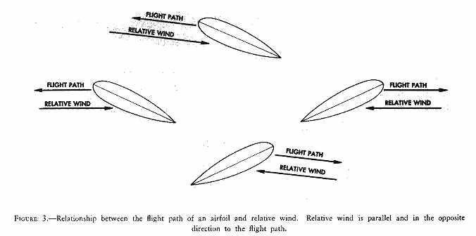
Relative wind - Relative wind is the direction of the airflow with respect to an airfoil. If an airfoil moves forward horizontally, the relative wind moves backward horizontally (fig. 3). If an airfoil moves backward horizontally, the relative wind moves forward horizontally. If an airfoil moves forward and upward, the relative wind moves backward and downward. If an airfoil moves backward and downward, the relative wind moves forward and upward. Thus, the flightpath and relative wind are parallel but travel in opposite directions. (Forward and backward as used here are relative to the fore and aft axis of the helicopter - forward meaning in the direction the nose of the helicopter points, and backward meaning the direction the tail points.)
Relative wind may be affected by several factors including the rotation of the rotor blades, horizontal movement of the helicopter, flapping of the rotor blades, and windspeed and direction.
Relative wind is created by the motion of an airfoil through the air, by the motion of air past an airfoil, or by a combination of the two. For a helicopter, the relative wind is the flow of air with respect to the rotor blades. When the rotor is stopped, wind blowing over the blades creates a relative wind; when the helicopter is hovering in a no-wind condition, relative wind is created by the motion of the rotor blades through the air; when the helicopter is hovering in a wind, the relative wind is a combination of the wind and the motion of the rotor blades through the air; and when the helicopter is in horizontal flight, the relative wind is a combination of the rotation of the rotor blades and the movement of the helicopter.
Figure 3 - Relationship between the flight path of an airfoil and relative wind. Relative wind is parallel and in the opposite direction to the flight path.
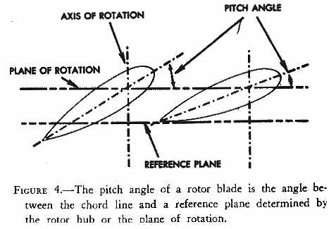
Pitch angle - The rotor blade pitch angle is the acute angle between the blade chord line and a reference plane determined by the main rotor hub. Since the rotor plane of rotation is parallel to the plane containing the main rotor hub, the rotor blade pitch angle could also be described as the acute angle between the blade chord line and the rotor plane of rotation (fig. 4). The pitch angle can be varied by the pilot through the use of cockpit controls (collective and cyclic pitch controls) provided for this purpose.
Figure 4 - The pitch angle of a rotor blade is the angle between the chord line and a reference plane determined by the rotor hub or the plane of rotation.
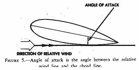
Angle of attack - The angle of attack is the angle between the chord line of the airfoil and the direction of the relative wind (fig. 5). The angle of attack should not be confused with the pitch angle of the rotor blades. The pitch angle is determined by the position of the appropriate cockpit controls (collective and cyclic pitch), whereas the angle of attack is determined by the direction of the relative wind. The angle of attack may be less than, equal to, or greater than the pitch angle as shown in figure 6. The pilot can increase or decrease the angle of attack by changing the pitch angle of the rotor blades. If the pitch angle is increased, the angle of attack is increased; if the pitch angle is decreased, the angle of attack is decreased. Since the angle of attack is dependent on the relative wind, the same factors that affect the relative wind also affect the angle of attack.
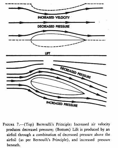
Lift - The force, lift, is derived from an airfoil through a principle often referred to as Bernoulli's Principle or the "venturi effect." As air velocity increases through the constricted portion of a venturi tube, the pressure decreases. Compare the upper surface of an airfoil with the constriction in the venturi tube (fig. 7). They are very similar. The upper half of the venturi tube is replaced by layers of undisturbed air. Thus, as air flows over the upper surface of an airfoil, the curvature of the airfoil causes an increase in the speed of the airflow. The increased speed of airflow results in a decrease in pressure on the upper surface of the airfoil. At the same time, airflow strikes the lower surface of the airfoil at an angle, building up pressure. The combination of decreased pressure on the upper surface and increased pressure on the lower surface results in an upward force. This is the force, lift.
Figure 5 - Angle of attack is the angle between the relative wind line and the chord line.
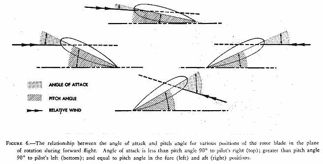
Figure 6 - The relationship between the angle of attack and pitch angle for various positions of the rotor blade in the plane of rotation during forward flight. Angle of attack is less than pitch angle 90° to pilot's right (top); greater than pitch angle 90° to pilot's left (bottom); and equal to pitch angle in the fore (left) and aft (right) positions.
Figure 7 - (Top) Bernoulli's Principle: Increased air velocity produces decreased pressure; (Bottom) Lift is produced by an airfoil through a combination of decreased pressure above the airfoil (as per Bernoulli's Principle), and increased pressure beneath.
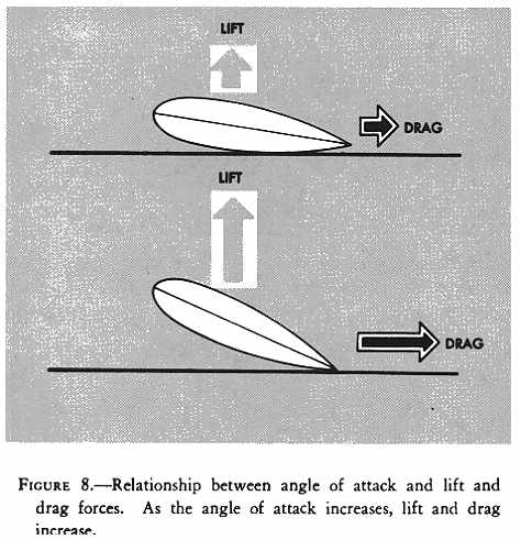
Drag (airfoil) - At the same time the airfoil is producing lift, it also is subject to a drag form. Drag is the term used for the force that tends to resist movement of the airfoil through the air - the retarding force of inertia and wind resistance. Drag acts parallel and in the opposite direction to the movement of the airfoil or, if you prefer, in the same direction as the relative wind. This force, drag, causes a reduction in rotor RPM (revolutions per minute) when the angle of attack is increased. An increase in angle of attack then not only produces an increase, in lift, but it also produces an increase in drag (fig. 8).
Figure 8 - Relationship between angle of attack and lift and drag forces. As the angle of attack increases, lift and drag increase.
Stall - When the angle of attack increases up to a certain point, the air can no longer flow smoothly over the top surface because of the excessive change of direction required. This loss of streamlined flow results in a swirling, turbulent airflow, and a large increase in drag. The turbulent airflow also causes a sudden increase in pressure on the top surface resulting in a large loss of lift. At this point, the airfoil is said to be in a stalled condition.
Lift and angle of attack - As the angle of attack of an airfoil increases, the lift increases (up to the stall angle) providing the velocity of the airflow (relative wind) remains the same (fig. 8). Since the pilot can increase or decrease the angle of attack by increasing or decreasing the pitch angle of the rotor blades through the use of the collective pitch cockpit control, lift produced by the rotor blades can be increased or decreased. The pilot must remember, however, that any increase in angle of attack will also increase drag on the rotor blades, tending to slow down the rotor rotation. Additional power will be required to prevent this slowing down of the rotor.
Lift and velocity of airflow - As the velocity of the airflow (relative wind) increases, the lift increases for any given angle of attack. Since the pilot can increase or decrease the rotor RPM which, in turn, increases or decreases the velocity of the airflow, the amount of lift can be changed. As a general rule, however, the pilot attempts to maintain a constant rotor RPM and changes the lift force by varying the angle of attack.
Lift and air density - Lift varies directly with the density of the air - as the air density increases, lift and drag increase; as air density decreases, lift and drag decrease.
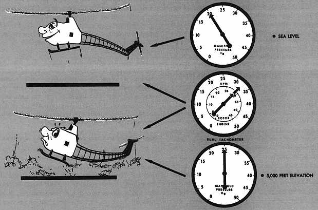
What affects air density? Altitude and atmospheric changes affect air density. The higher the altitude the less dense the air. At 10,000 feet the air is only two-thirds as dense as the air at sea level. Therefore, if a helicopter is to maintain its lift, the angle of attack of the rotor blades must be increased. To increase the angle of attack, the pilot must increase the pitch angle of the blades. We have already seen that, as the pitch angle increases, drag on the rotor system increases and the rotor RPM tends to decrease. Therefore, more power must be applied to prevent a decrease in rotor RPM. This is why a helicopter requires more power to hover at higher altitudes than under the same conditions at lower altitudes. (See fig. 52 and the accompanying discussion.)
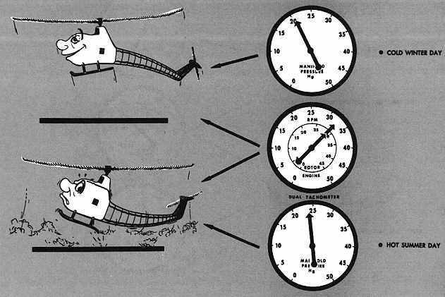
Due to the atmospheric changes in temperature, pressure, or humidity, the density of the air may be different, even at the same altitude, from one day to the next or from one location in the country to another. Because air expands when heated, hot air is less dense than cold air. For the helicopter to produce the same amount of lift on a hot day as on a cold day, the rotor blades must be operated at a higher angle of attack. This requires that the blades be operated at a greater pitch angle which increases rotor drag and trends to reduce rotor RPM. Therefore, to maintain a constant rotor RPM, more throttle is required. For this reason, a helicopter requires more power to hover on a hot day than on a cold day. (See fig. 53 and the accompanying discussion.)
Since air expands as pressure is decreased, there will be fluctuations in the air density due to changes in atmospheric pressure. The lower the pressure, the less dense the air and, for the same reason stated previously, the greater the power required to hover.
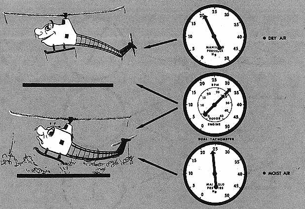
Because water vapor weighs less than an equal amount of dry air, moist air (high relative humidity) is less dense than dry air (low relative humidity). Because of this, a helicopter will require more power to hover on a humid day than on a dry day (see fig. 54 and the accompanying discussion). This is especially true on hot, humid days because the hotter the day, the greater the amount of water vapor the air can hold. The more moisture (water vapor) in the air, the less dense the air.
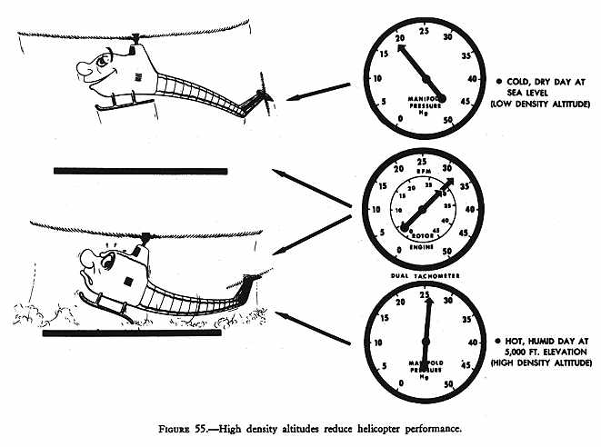
From the above discussion, it is obvious that a pilot should beware of high, hot, and humid conditions - high altitudes, hot temperatures, and high moisture content (see fig. 55 and the accompanying discussion). A pilot should be especially aware of these conditions at the destination, since sufficient power may not be available to complete a landing safely, particularly when the helicopter is operating at high gross weights (see fig. 64 and the accompanying discussion).
Lift and weight - The total weight (gross weight) of a helicopter is the first force that must be overcome before flight is possible. Lift, the force which overcomes or balances the force of weight, is obtained from the rotation of the main rotor blades.
Thrust and drag - Thrust moves the aircraft in the desired direction; drag, the retarding force of inertia and wind resistance, tends to hold it back. In vertical flight, drag acts downward; in horizontal flight, drag acts horizontally and opposite in direction to the thrust component. Thrust, like lift, is obtained from the main rotor. Drag, as discussed here, is the drag of the entire helicopter - not just the drag of the rotor blades which was discussed earlier. The use of the term "drag" in subsequent portions of this handbook should be considered as having this same connotation. In future references to the drag of the rotor blades, the statement "drag of the rotor blades or rotor system" will be used.